Code Generation from Simulink Models with GPU Coder
GPU Coder™ generates optimized CUDA® code from Simulink® models containing MATLAB Function blocks. You can use the generated code and executable for rapid prototyping on NVIDIA® GPUs. Code generation reports and traceability enable you to view and analyze the generated code. The basic steps for CUDA code generation by using GPU Coder are:
Create or open a model.
Configure the model for code generation by selecting the solver, language, toolchain, and other GPU-specific configuration parameters.
Build the model.
Example: Sobel Edge Detection
The Sobel edge detection algorithm is a simple edge detection algorithm that performs a 2-D spatial gradient operation on a grayscale image. This algorithm emphasizes the high spatial frequency regions that correspond to the edges of the input image.
The Sobel edge algorithm computes the horizontal gradient (H) and the vertical gradient (V) of the input image by using two orthogonal filter kernels (k and k'). After the filtering operation, the algorithm computes the gradient magnitude and applies a threshold to find the regions of the images that are considered to be edges.
k = single([1 2 1; 0 0 0; -1 -2 -1]);
H = conv2(single(grayImage),k, 'same');
V = conv2(single(grayImage),k','same');
E = sqrt(H.*H + V.*V);
edgeImage = uint8((E > threshold) * 255);

Create Edge Detection Model
Create a Simulink model and insert two MATLAB Function blocks from the User-Defined Functions library.
Add a Constant block and set its value to
0.4.Add a From Multimedia File block from the Computer Vision Toolbox™ library.
Open the Block Parameters dialog box for the From Multimedia File block and set the File name parameter to
rhinos.avi.Set the Image signal parameter to
One multidimensional signal.Add two Video Viewer blocks from the Computer Vision Toolbox library to the model.

Double-click on one of the MATLAB Function blocks. A default function signature appears in the MATLAB Function Block Editor.
Define a function called
sobel, which implements the Sobel edge detection algorithm. The function header declaresgrayImageandthresholdas an argument to thesobelfunction, withedgeImageas the return value. Save Editor document to file.function edgeImage = sobel(grayImage,threshold) %#codegen % Define Kernel for Sobel edge detection k = single([1 2 1; 0 0 0; -1 -2 -1]); % Detect Edge H = conv2(single(grayImage),k, 'same'); V = conv2(single(grayImage),k','same'); E = sqrt(H.*H + V.*V); edgeImage = uint8((E > threshold) * 255); end
Open the block parameters for the MATLAB Function block. On the Code Generation tab, select
Reusable
              function
for Function packaging parameter.If the Function packaging parameter is set to any other value, CUDA kernels may not get generated.
Modify the other MATLAB Function block to implement the RGB to grayscale conversion prior to the Sobel edge detection operation. Set the Function packaging parameter of the MATLAB Function block to
Reusable function.function gray = RGB2gray(RGB) %#codegen % Convert color image to grey image gray = (0.2989 * double(RGB(:,:,1)) + ... 0.5870 * double(RGB(:,:,2)) + ... 0.1140 * double(RGB(:,:,3))); end
Connect these blocks as shown in the diagram. Save the model as
edgeDetection.slx.
To test the model for errors, simulate the model in the Simulink Editor. On the toolstrip, click Run.
To see all video frames during simulation, disable the Simulation > Drop Frames to improve Performance option of the Video Viewer block.

Configure Model for Code Generation
The model configuration parameters provide many options for the code generation and build process.
Open the Configuration Parameters dialog box. Open the Solver pane. To compile your model for acceleration and generate CUDA code, configure the model to use a fixed-step solver. This table shows the solver configuration for this example.
Parameter Setting Effect on Generated Code Type Fixed-stepMaintains a constant (fixed) step size, which is required for code generation Solver discrete (no continuous states)Applies a fixed-step integration technique for computing the state derivative of the model Fixed-step size autoSimulink chooses the step size 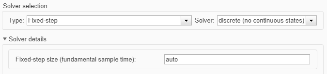
On the Code Generation pane, set the System target file to
grt.tlc.You can also use the Embedded Coder® target file
ert.tlcor a custom system target file.For GPU code generation, the custom target file must be based on
grt.tlcorert.tlc. For information on developing a custom target file, see Customize System Target Files (Simulink Coder).Set the Language to
C++.Select Generate GPU code.
On the Code Generation pane, select Generate code only.
Select the Toolchain. For Linux® platforms, select
NVIDIA CUDA | gmake (64-bit
              Linux)
. For Windows® systems, selectNVIDIA CUDA (w/Microsoft Visual C++ 20XX) | nmake (64-bit windows).When using a custom system target file, you must set the build controls for the toolchain approach. To learn more about toolchain approach for custom targets, see Support Toolchain Approach with Custom Target (Simulink Coder).
On the Code Generation > Interface pane, disable MAT-file logging.
On the Code Generation > Report pane, select Create code generation report and Open report automatically.
When you enable the Generate GPU code parameter, options specific to GPU Coder appear in the Code Generation > GPU Code pane.
For this example, you can use the default values of the GPU-specific parameters in Code Generation > GPU Code pane.

Click OK to save and close the Configuration Parameters dialog box.
You can use the
set_paramfunction to configure the model parameter programmatically in the MATLAB® Command Window.set_param('edgeDetection','GenerateGPUCode','CUDA');
Generate CUDA Code for the Model
In the Simulink Editor, open the Simulink Coder app.
Generate code.
Messages appear in the Diagnostics Viewer. The code generator produces CUDA source and header files, and an HTML code generation report. The code
generator places the files in a build folder, a subfolder
named edgeDetection_grt_rtw under your current working folder.
You can find the CUDA kernels in the <model_name>_eML_blk_kernel and
<model_name>_eML_blk_kernel_c functions. The information within the
triple chevrons is the execution configuration for the kernel.
Limitations
GPU code generation for MATLAB Function blocks in Stateflow® charts is not supported.
The MATLAB Function block does not support all the data types from the MATLAB language. For supported data types, refer to the block documentation.
For GPU code generation, the custom target file must be based on
grt.tlcorert.tlc.
See Also
Functions
open_system(Simulink) |load_system(Simulink) |save_system(Simulink) |close_system(Simulink) |bdclose(Simulink) |get_param(Simulink) |set_param(Simulink) |sim(Simulink) |slbuild(Simulink)
Related Topics
- Simulation Acceleration by Using GPU Coder
- GPU Code Generation for Deep Learning Networks Using MATLAB Function Block
- GPU Code Generation for Blocks from the Deep Neural Networks Library
- Targeting NVIDIA Embedded Boards
- Numerical Equivalence Testing
- Parameter Tuning and Signal Monitoring by Using External Mode
- GPU Code Generation for Lane Detection in Simulink
- GPU Code Generation for a Fog Rectification Simulink Model
You can also select a web site from the following list:
Americas
- América Latina (Español)
- Canada (English)
- United States (English)
Europe
- Belgium (English)
- Denmark (English)
- Deutschland (Deutsch)
- España (Español)
- Finland (English)
- France (Français)
- Ireland (English)
- Italia (Italiano)
- Luxembourg (English)
- Netherlands (English)
- Norway (English)
- Österreich (Deutsch)
- Portugal (English)
- Sweden (English)
- Switzerland
- United Kingdom (English)