Stateflow® provides a graphical language that includes state transition diagrams, flow charts, state transition tables, and truth tables. You can use Stateflow to describe how MATLAB® algorithms and Simulink® models react to input signals, events, and time-based conditions.
Stateflow enables you to design and develop supervisory control, task scheduling, fault management, communication protocols, user interfaces, and hybrid systems.
With Stateflow, you model combinatorial and sequential decision logic that can be simulated as a block within a Simulink model or executed as an object in MATLAB. Graphical animation enables you to analyze and debug your logic while it is executing. Edit-time and run-time checks ensure design consistency and completeness before implementation.
Get Started:

Free Interactive Course
Stateflow Onramp
Designing State Machines Graphically
Build state machines graphically by drawing states and junctions connected by transitions. You can also create functions using flow chart notation, Simulink subsystems, MATLAB code, and truth tables.

Stateflow diagram defining the logic for a boiler temperature control system. The diagram uses graphical functions (right side) to implement utility algorithms called by the heater system (left side).
Designing Flow Charts
Create flow charts by drawing transitions that are connected at junctions. The Pattern Wizard lets you create commonly used logic flow patterns. You can use flow charts to design logic for transitioning between states.

Represent combinatorial logic such as decision trees and iterative loops graphically with flow charts.
Designing Logic with Tables
Truth tables in Stateflow let you model logic in Simulink when the output depends purely on the current input. State transition tables provide a structured environment for modeling state machines in Simulink.

Truth table implementing the logic for selecting a valid sensor reading in a fault-detection algorithm.
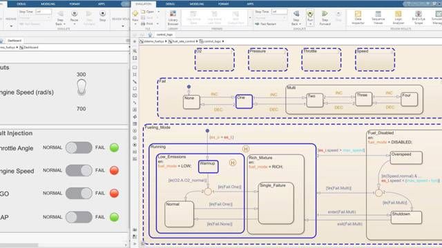
Executing Stateflow Charts
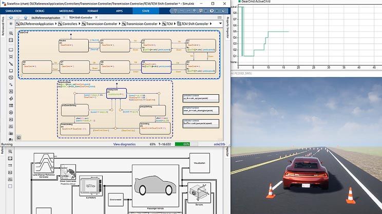
Visualize system behavior using state diagram animations to highlight active states and transitions in your charts.
Debugging Stateflow Charts
Stateflow debugging capabilities let you step through chart execution in detail. You can set breakpoints, monitor data values, and step through different functions in your state diagrams.

Simulation data visualization options in Stateflow. Top left: Simulink Data Inspector for comparing specific signals; bottom left: custom MATLAB interface for analyzing data; right: Simulink Signal Selector for comparing specific states.
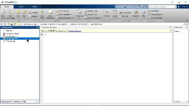
Reusable Chart Objects
Create standalone Stateflow charts that use the full capabilities of the MATLAB language in state and transition actions. Use these charts as MATLAB objects in your applications that require state machine and timing logic.
State Machine and Timing Logic
Accelerate the development of MATLAB applications by using Stateflow to graphically design state machine and timing logic that would be difficult to implement textually.
Deploying Stateflow Applications
Create MATLAB applications that include Stateflow chart objects and share them without requiring Stateflow.

Share MATLAB applications that include Stateflow chart objects with users who do not have Stateflow.
Periodic and Continuous Scheduling
You can model conditional, event-based, and time-based logic in Stateflow to invoke Simulink algorithms in a periodic or continuous manner. Orchestrate the execution of components to simulate the scheduling of your real-time environment.

You can model logic in Stateflow to call Simulink and MATLAB algorithms in a periodic or continuous manner.
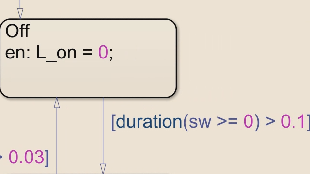
Temporal Operators
Use event-based and time-based operators (such as after and duration) to specify state-transition logic based on event counts, elapsed time, and denoised signals without having to create and maintain your own timers and counters.
Validating Designs
Use Stateflow with other Simulink products to validate your design against requirements.
- Link requirements directly to Stateflow objects using drag and drop with Requirements Toolbox™.
- Check that your state diagrams comply with standards using Simulink Check™.
- Collect model and generated code coverage metrics with Simulink Coverage™.
- Detect design errors and generate test vectors using Simulink Design Verifier™.
- Develop, manage, and execute simulation-based tests with Simulink Test™.

Highlight Active Logic using Model Slicer.
Generating Code
Generate code for implementation of your Stateflow logic on embedded systems.
- Generate C and C++ code from Simulink and Stateflow models using Simulink Coder™.
- Generate VHDL and Verilog code for FPGA and ASIC designs with HDL Coder™.
- Generate IEC 61131-3 Structured Text for PLCs and PACs using Simulink PLC Coder™.

Generate code to implement Stateflow logic.
Product Resources:
What's Next?


You can also select a web site from the following list
Americas
- América Latina (Español)
- Canada (English)
- United States (English)
Europe
- Belgium (English)
- Denmark (English)
- Deutschland (Deutsch)
- España (Español)
- Finland (English)
- France (Français)
- Ireland (English)
- Italia (Italiano)
- Luxembourg (English)
- Netherlands (English)
- Norway (English)
- Österreich (Deutsch)
- Portugal (English)
- Sweden (English)
- Switzerland
- United Kingdom (English)
Asia Pacific
- Australia (English)
- India (English)
- New Zealand (English)
- 中国
- 日本Japanese (日本語)
- 한국Korean (한국어)